Design Process – ATR Chassis & MIL-Spec Enclosures:
With applications becoming more demanding and processor speeds / heat loads increasing with every new generation of products released it becomes more and more important to consider thermal management at the onset of a design project. Particularly in conduction or hybrid cooled ATR Chassis and air cooled MIL-Spec Rackmount Chassis, thermal design is key.
- Gather or review product specifications and application
- Create preliminary model of ATR or rackmount chassis with major components defined
- Run a preliminary thermal analysis assign the maximum heat load to all plug in boards, power supplies, and components while using the maximum operating temperature and altitude in a steady state. This will represent the worse-case operating environment and the baseline for the thermal design.
- With this design baseline the ATR heatsink fins are modified, fans are selected, and so on to create an updated preliminary model which will meet the worse-case operation environment with sufficient margin.
- Generally at this point a preliminary design review is conducted to approve the direction and assumptions made. NIS will recommend any updates to the enclosure size, power system, cooling system, etc. to make a compliant system.
- From here, the design will be reduced in size/weight as much as possible while maintaining the thermal goals and proper structure. Iterative thermal and structural analysis are conducted to validate the final design.
- The final design is presented to the customer at a Critical Design Review with all pertinent thermal and structural simulations ready.
Our goal in all designs is to increase thermal conductivity and performance, reduce size and weight, and produce an enclosure which is highly reliable, inexpensive and easy to maintain.
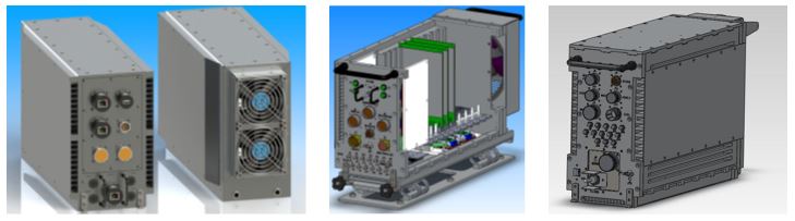
ATR design from initial concept, to preliminary thermal model, to final design prior to production
Design Process – Ruggedized Electronics:
Ruggedizing commercial electronics for Military applications or harsh environments is a specialty of Nova Integration Solutions and a design process with its own unique challenges. Examples of this expertise can be found in our 1000 Series Rugged & MIL-Spec Printers, 4000 Series Enclosures and 6000 Series Electronics Enclosures.
This design process starts by assessing the commercial electronics (print engine, ATX motherboard, commercial power supply, KVM device, Ethernet switch, etc.) and comparing the testing results to the required program specifications. These electronic devices are stripped of the commercial grade housings and subjected to temperature extremes, heavy vibration over a full frequency range, and subjected to aggravated power loads. Engineers take note of hot spots to provide additional cooling or weak areas which require added structure. In this iterative process, parts are pushed to failure, repaired, and tested again. Often, substandard components or materials are used which can cause failures, reduced reliability, or provide hazardous in dangerous operating conditions. NIS engineers have the experience and knowledge to understand and overcome these inherent challenges.
- “Tear down” the commercial electronics discarding unneeded material
- Assess commercial electronics and subject to aggravated environmental test
- Create preliminary model of printer or enclosure utilizing information gathered in testing
- Run a preliminary thermal and structural analysis which will represent the worse case operating environment and the baseline for the overall design.
- Generally at this point a preliminary design review is conducted to approve the direction and assumptions made. NIS will recommend any updates to the enclosure size, power system, cooling system, etc. to make a compliant system. Note, in some cases the commercial electronics are simply not suitable for ruggedization at which point NIS can recommend an equivalent or simply design the desired item using proper engineering standards.
- The enclosure will be reduced in size/weight while maintaining the thermal goals and proper structure. Iterative thermal and structural analysis are conducted to validate the final design.
- The final design is presented to the customer at a Critical Design Review with all pertinent thermal and structural simulations ready.
- Prior to production, a ruggedization plan is created to inform assembly staff how to tear down the electronics and further ruggedize them prior to installation in the mil-spec enclosure.
Our goal in all designs is to increase thermal conductivity and performance, reduce size and weight, and produce an enclosure which is highly reliable, inexpensive and easy to maintain. Ruggedizing commercial electronics has the added goal of providing a final product which is familiar to a broad base of users with replacement parts and support very readily available.
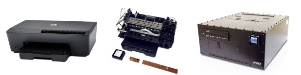
Rugged Printer design from COTS print engine, to “tear down”, to MIL-Spec Printer Enclosure
Design & Simulation Tools:
All enclosures are modeled using the SolidWorks 3D CAD tool set. A mass analysis and a structural Finite Element Analysis (FEA) is performed to include thermal simulations to validate compliance to the customer specifications. A 3D CAD model is then produced for customer review during the PDR and CDR review processes. The design is subject to Customer approval prior to the production of a First Article Unit (FAU). When approved, subsequent production units are then produced.
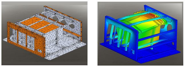
Modular power supply design: Right image shows mesh array. Left image shows the exaggerated deflection from a shock simulation.
NIS enclosures are designed to provide high-reliability and are often subjected to extremely harsh environments such as shock and vibration, high altitudes, extreme temperature ranges, EMI/RFI, HEMP, nuclear/chemical survivability, salt, fog, humidity, water, sand/dust and explosive atmosphere. Optional certification and functional testing can be performed by the Customer or by NIS when appropriate.
NIS will design these enclosure to meet a variety of specifications for harsh Environments i.e,
MIL-STD-461, MIL-S-901, MIL-STD-167, MIL-STD-810, DO-160, Tempest, just to name a few.
General Design Goals:
- High MTBF
- Low MTTR
- Increased efficiency; Size, Weight and low Power consumption (SWaP)
- Optimized cooling
- Ease of use and serviceability
- Reduced total cost of ownership
Carbon Fiber Materials – New Solutions to Old Problems:
NOVA Integration Solutions now offers Carbon Fiber (CF) as an alternative to traditional enclosure materials. It can be used to minimize size, reduce weight, increase strength, and to improve thermal performance. Note that the use of thermally conductive CF is still in its infancy and is a new conceptual feature being developed by NIS.
A variety of conductive CF and non-conductive composite materials exist can be used with our enclosures. A family of light-weight shock trays using composite CF materials is being developed by NIS.
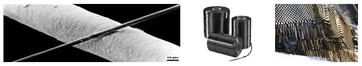
A 6 μm diameter carbon filament running from bottom left to top right as compared to a human hair.
PAN Carbon Fiber
NIS has begun to use synthetic PAN CF composite materials to lighten our enclosures and shock trays. These materials are light and strong.
A weight savings estimated at 50% can be achieved.
PITCH Carbon Fiber
Thermally-conductive isotropic and unidirectional continuous PITCH CF materials are being used to improve thermal performance and to lighten an ATR chassis beyond aluminum through a process known as Flatware.
This cost-effective process developed by NIS is an alternative to molding and involves the use of thermally-conductive CF materials bonded together with aluminum to produce a hybrid solution without the need for expensive tooling. An ideal way to replace heavy parts with drop-in alternatives that can improve thermal performance and lighten the ATR and without redesigning the enclosure.
A weight savings estimated at 25% – 30% can be achieved.
Increased thermal management estimated at 2X – 3X can be achieved.
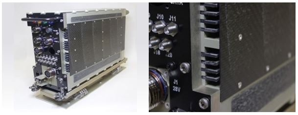
A hybrid cooled ATR Chassis prototype utilizing retrofitted thermally conductive carbon fiber on the chassis side walls. This ATR prototype reduced weight by approximately 25% while maintaining the thermal conductivity using the lowest grade thermally conductive carbon fiber.